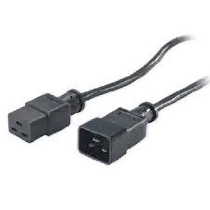
APC AP9879 2m

£29.86

Description

Power Cable, No, IEC C13, IEC C20, Black

APC AP9879 2m properties

Product name AP9879 2m
Type Power Cable
Grounded No
Cable Length 2.0 m
Contact for Power Source IEC C20
Connector IEC C13
Maximum Power (without spikes) 10.0 A
Colour Black
Weight 360.0 g

Additional information

Product name

Product type

Grounded

Cable Length

Contact for Power Source

Connector

Maximum Power

Colour

Weight

Reviews

There are no reviews yet.

Be the first to review “APC AP9879 2m”

Your email address will not be published. Required fields are marked *

Frequently Asked Questions:

"How do I properly install and configure the APC AP9879 2m power cord for my computer?"

First, ensure that your computer meets the necessary requirements to use the APC AP9879 power cord. The cord is compatible with computers that require a standard IEC C13 connector and NEMA L5-20R outlet. Check your computer's specifications to confirm this information. Next, gather the necessary tools for installation. You will need a screwdriver or a similar tool to attach the cord securely to the back of your computer case. If you have not already done so, also ensure that there is sufficient space behind your computer for the length of the cord (the AP9879 has a 2-meter length). Connect one end of the power cord to the AC outlet or surge protector where you will be using your computer. The other end should be connected to your computer's power supply, which is typically located at the back of your computer case. Be sure that the connector on your computer matches the C13 connector on the end of the cord. Before turning on your computer, ensure that the cord is securely attached and that there are no loose connections. If you notice any damage or defects in the cord, do not use it and contact APC customer support for assistance. Finally, configure your computer's operating system to recognize the new power supply. This may involve updating your computer's BIOS settings or configuring your operating system's power management options to ensure that your computer is properly powered by the AP9879 power cord. Consult your computer's user manual for specific instructions on how to do this. Once you have completed these steps, turn on your computer and confirm that it is running smoothly with the new power supply. If you encounter any issues or have further questions about installing or configuring the AP9879 power cord, contact APC customer support for assistance.

"How do I properly configure and test the APC AP9879 2m PoE+ injector for use with my network devices?"

Gather the necessary equipment:
- APC AP9879 PoE+ injector
- Network device(s) that support PoE+ (Power over Ethernet Plus)
- CAT6 or higher Ethernet cables
- Power source for the AP9879 (either AC adapter or compatible PoE switch)
- A computer or network analyzer to test connectivity and power delivery

2. Connect the AP9879 to a power source:
- If using an AC adapter, plug it into the wall outlet and connect it to the AP9879's DC input port (located on the rear of the device). If connecting directly to a PoE switch, use a CAT6 or higher Ethernet cable to connect the injector's output port (also located on the rear) to an open PoE+ port on the switch. Connect the network device(s):
- Use a CAT6 or higher Ethernet cable to connect each network device to one of the AP9879's 12 ports (located on the front). Make sure that the devices are properly identified and configured in your network management software. Test connectivity:
- Use a computer or network analyzer to ping each connected device to ensure that they can communicate with one another and with the rest of your network. Check your network logs for any errors or warnings related to PoE+ power delivery. Verify power delivery:
- Use a multimeter or a compatible PoE tester (such as APC's own PT7230) to measure the voltage and current being delivered to each connected device. Check that the injector is delivering the correct amount of power for your specific devices, according to their PoE+ specifications. Optimize performance:
- Consider configuring the AP9879's PoE+ settings to match the needs of your network devices, such as adjusting the power budget or enabling/disabling specific ports. Regularly monitor the injector and your network devices for any issues related to power delivery, connectivity, or performance. By following these steps, you should be able to properly configure and test the APC AP9879 PoE+ injector for use with your network devices. If you encounter any problems or have further questions, refer to the device's user manual or contact APC support for assistance.

How do I properly install and configure an APC AP9879 2m network management card in my server to manage power distribution units remotely using SNMP protocol?

Gather the necessary tools and components:
- APC AP9879 Network Management Card (P/N 0624-AP9879)
- Server with available PCI slot
- Screwdriver or other appropriate tool for opening server case
- Ethernet cable
- Computer with SNMP management software (such as HP OpenView, SolarWinds, or PRTG Network Monitor) and network connectivity to the server
2. Power off and open the server case:
- Ensure that the server is powered down and all power cords are unplugged. Use a screwdriver or other appropriate tool to remove the case panels covering the PCI slot where the AP9879 card will be installed. Follow manufacturer's instructions for your specific server model. Insert the AP9879 card into the PCI slot:
- Align the AP9879 card with the PCI slot and firmly press it in until it clicks into place. Connect the Ethernet cable:
- Connect one end of an Ethernet cable to the "LAN" port on the back of the AP9879 card, and connect the other end to a switch or router on your network. Power on the server:
- Close the case panels and ensure that all power cords are securely connected. Power on the server and wait for it to fully boot up. Configure the AP9879 card:
- Connect to the server using SNMP management software, such as HP OpenView or SolarWinds Network Performance Monitor. Follow the instructions provided by your specific SNMP management software to add the AP9879 card and configure it for remote monitoring and management of APC PDU units via SNMP protocol. Test the connection:
- Use the SNMP management software to ping the IP address assigned to the AP9879 card and verify that it responds. Use the SNMP management software to poll the AP9879 card for information about connected PDU units and their power usage. Configure the APC PDUs:
- Connect your APC PDUs to the AP9879 card and ensure that they are properly configured and powered on. Use the SNMP management software to remotely monitor and manage the connected PDUs, including setting thresholds for alerts, scheduling power cycles or shutdowns, and viewing detailed energy usage reports.

How do I properly install the RCBO in my house, and what are the implications if I incorrectly wire it?

1. Identify the Correct RCBO: Before starting, ensure you have selected a suitable RCBO for your application. You can determine this by consulting with an electrician or referring to industry guidelines, such as those provided by the Institute of Electrical and Electronics Engineers (IEEE). Disconnect Power: Switch off the main electrical supply to the circuit at the distribution board before starting work. Verify that the power is disconnected using a voltage tester. Identify the Circuit: Confirm the circuit you are working on and verify its intended function. This information can be found on the RCBO's label or in your home's wiring diagram. Remove Old Devices (If Necessary): If replacing an existing device, remove any old devices and disconnect all cables from the socket outlet. Connect New RCBO: Mount the new RCBO on a suitable bracket, ensuring it's securely fastened to prevent movement. Ensure the RCBO is correctly polarized according to its label. Connect Wires: Carefully connect the wires to their respective terminals. Remember that green/yellow wires (earth) are always connected to the earth terminal of the RCBO and must not be reversed. Secure the RCBO: Once all connections have been made, secure the RCBO with its bracket or any additional mounting hardware provided by the manufacturer. Test the RCBO: After installation, test the RCBO by simulating a fault condition (using a low voltage source) on the circuit and verifying that it trips correctly.